GATE 2020
1. Ten equisplaced metal electrodes are arranged along a profile for multi-electrode 2D resistivity imaginary survey. If Wenner array is used for data recording, the maximum number of observations will be
(a) 7 (b) 11 (c) 12 (d) 13
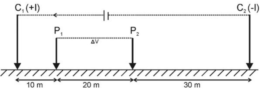
2. Current and potential electrodes in resistivity survey over an inhomogeneous ground is shown in the shown in the figure below. If 100mA current flow between C1 and C2 generates 50mV potential difference between P1 and P2 , then the apparent resistivity of the medium will be ____ohm-m. (Round off to 2 decimal places) (Use \(\pi=3.14\))
3. The means the resistivity of a horizontally stratified cuboid rock sample is 100 oohm- m and coefficient of electrical anisotropy is 1.15. The transverse resistivity of the rock sample_____ohm-m. (Round off 2 decimal places)
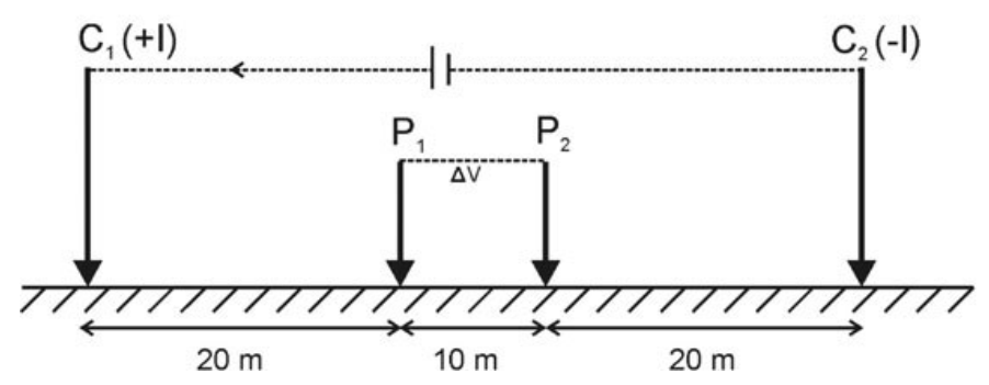
4. The ‘Geometrical factor’ for the electrode configuration given below will be _______ m. (Round off to 2 decimal places) (Use \(\pi = 3.14\)) (C1 and C2 are current electrodes; P1 and P2 are potential electrodes)
GATE 2019
1. The difference in the mobility of ions in the electrolyte and electrons in metallic conductors in the sub-surface due to applied external electric field gives rise to _________ .
(a) electrode polarization (b) membrane polarization
(c) electro-kinetic potential (d) electro-chemical potential
2. A massive sulphide body in the subsurface is partially above the water table. According to the pH variation hypothesis for the origin of Self Potential, which one of the following statements is CORRECT for such a body?
(a) Acidic above and basic below the water table.
(b) Basic above and acidic below the water table.
(c) Acidic above and below the water table.
(d) Basic above and below the water table.
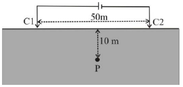
3. A pair of current electrodes C1 (+I) and C2 (–I) is placed 50m apart (shown in the figure below) over a homogeneous structure of resistivity 100 ohm-m and 1 Ampere current flows through the subsurface. Which one of the following is CORRECT for the potential (Vp ) and horizontal component of electric field (Ex) at a point P located exactly below the midpoint between Cl and C2 at a depth of 10 m?
(a) Vp = 0 and Ex = 0 (b) Vp = 0 and Ex \(\neq\) 0
(c) Vp \(\neq\) 0 and Ex = 0 (d) Vp \(\neq\) 0 and Ex \(\neq\) 0
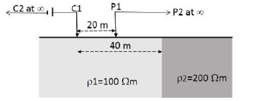
4. A Two-electrode array is placed over a vertical contact (2-D) as shown in the given figure (strike of contact is perpendicular to the plane of paper). If 1 Amp current flows through the subsurface, then the potential at the potential electrode PI will be ____ millivolts. (round off to the nearest integer). (Consider structures with resistivity \(\rho_1\) and \(\rho_2\) to be laterally extending to infinity on both sides of the contact and also in the downward direction, C2 and P2 are grounded at infinity) (Use \(\pi\) = 3.14)
3. In an electrical resistivity imaging survey, Axial Dipole-dipole array is placed over an inhomogeneous structure. The centers of current and potential dipoles are separated by a distance of 100 m. The length of each dipole is 10 m. If 5 Amp current flows through the subsurface and 50 mV potential difference is measured across the potential dipole then apparent resistivity will be ________ ohm-metres, (round off to the nearest integer) (Use \(\pi\) = 3.14)
GATE 2018
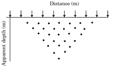
1. Multi-electrode resistivity survey is carried out by placing 10 equispaced electrodes (denoted by arrows in the figure below) on the surface of the earth. The points of observations in the distanceapparent depth plane are marked as solid dots in the figure shown below. Considering the mid-point of the 4-electrode array as the point of observation in the lateral direction, identify the CORRECT electrode configuration used for the survey.
(a) Multi-electrode Wenner array. (b) Multi-electrode Axial Dipole-dipole array.
(c) Multi-electrode Wenner-Schlumberger array. (d) Multi-electrode Axial Pole-dipole array
2. A student interpreted a four layer Schlumberger resistivity sounding data and obtained the resistivities (ohm) and thicknesses (h) as follows: p1 = 100 ohm-m, p2 = 20 ohm-m, p3 = 1500 ohm-m and p4 = 50 ohm-m; h1 = 50 m, h2 =10 m and h3 =20 m. The same data is interpreted by another student who obtains p3 = 2000 ohm-m. Then, according to the principle of equivalence, the value of h3 interpreted by the second student is ________m. (All other model parameters estimated by both the students are the same.)
3. The apparent resistivities obtained at 0.1 Hz and 10 Hz in the frequency domain I.P. measurement are 100 ohm-m and 80 ohm-m, respectively. The Percentage Frequency Effect is _________.
GATE 2017
2. The apparent resistivity for Wenner and Schlumberger configurations in an electrical sounding experiment is the same for a certain electrode spacing ‘a’ (Wenner configuration). Given the current electrode spacing of 18 m and the potential electrode spacing of 2 m for a Schlumberger configuration, the value of ‘a’ is ________m.
3. In a time-domain (TD) induced polarization experiment with a steady voltage of 10 mV during the current flow interval, the voltage decay after the current cut-off is given by \(v(t) = 4.0 \ e^-{0.3t}\) mV. The chargeability after current cut-off between t1 = 1 s and t2 = 4 s is __________ ms.
GATE 2016
GATE 2015
1. In which one of the following configurations the electrodes are uniformly spaced?
(a) Schlumberger array
(b) Pole-dipole array
(c) Wenner array
(d) Pole-pole array
2. Which type of VES curve is obtained for a three layered earth model consisting of wet shale (top layer), poorly water saturated sandstone (middle layer) and impermeable granite (bottom layer)?
(a) K (b) Q (c) H (d) A
3. In frequency domain IP, which one of the following frequency ranges (in Hz) is used to measure apparent resistivity at DC and AC limits?
(a) 0.01 – 0.1
(b) 0.1 – 1
(c) 0.1 – 10
(d) 10 – 100
GATE 2014
1. The reflection coefficient at the interface between two layers of resistivities 9 ohm-m and 1 ohm-m respectively is
(a) 0.6 (b) 0.7 (c) 0.8 (d) 0.9
2. Compute the coefficient of anisotropy from the following parameters estimated from a Vertical Electric Sounding (VES) survey.
Resistivity of first layer, p1 = 15 ohm-m
Resistivity of second layer, p2 = 4 ohm-m
Resistivity of lower half-space, p3 = 50 ohm-m
Thickness of first layer, h1 =3m
Thickness of second layer, h2 =16m
(a) 1.43 (b) 1.28 (c) 1.19 (d) 1.13
3. Arrange the following electrode configurations in the ascending order of their depth of investigation (P) Dipole-Dipole (Q) Schlumberger (R) Wenner (S) Pole-Pole
(a) R – S – Q – P (b) P – Q – S – R (c) R – Q – P – S (d) R – Q – S – P
GATE 2013
GATE 2012
GATE 2011
GATE 2010
GATE 2009
GATE 2018
GATE 2018
